3-D Printing Design: Five Tips to Achieve Additive Manufacturability
3-D printing, also known as additive manufacturing, is quickly becoming a widely embraced technology, with companies using it for prototyping and low-volume part production and hobbyists and do-it-yourselfers purchasing smaller machines for creating customized parts on their own.
With all of the excitement about the possibilities of 3-D printing, it is important to know how to design parts for this technology.
Additive manufacturing systems have distinct differences from other manufacturing methods and you don’t have to follow many traditional design-for-manufacturability rules.
The result is the freedom to create parts that are designed solely for form, fit and function. By breaking free from previous design constraints, 3-D printing is making companies more efficient and lowering costs.
1. Breaking Away from Traditional Manufacturing Constraints
For years, engineers have been taught to design products around how the production parts will be manufactured, such as injection molding or subtractive manufacturing processes, which has hindered design freedom.
With injection molding, there are a number of requirements that limit part design: draft angles to ensure proper ejection from the mold, radiused corners for reduced stress, uniform wall thicknesses and part size limitations—just to name a few.
Likewise, CNC machining limits the production of complex geometries like internal channels because there is no path for the tool to reach inside the part. And intricate components like undercuts and overhangs often require multiple set-ups and secondary operations, driving up costs and causing production delays.
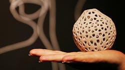
Yet, none of these limits exist in additive manufacturing because parts are built from the ground up, layer by layer with soluble support structures. You can build complex parts with multiple components like internal channels, holes, lattice structures and mid-build inserts, which would need to be created separately in traditional manufacturing, increasing the time and expense of building parts.
There is also a wide range of additive manufacturing technologies that can support almost any part: PolyJet can produce fine feature details and multiple materials ideal for realistic prototypes; and Fused Deposition Modeling (FDM) builds parts with the same engineering-grade thermoplastics used for injection molding, which are durable enough for functional testing and demanding end-use applications.
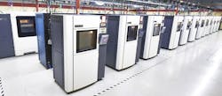
The size of your part is also not an issue with 3D printing. The largest Stratasys FDM machine builds parts up to 36 x 24 x 36 in., but if the part is larger the design file can be split into multiple pieces, with each piece built on a separate machine and then hot air welded or bonded together, giving it the strength and functionality as if it was a single part.
The End of Tooling Cost
2. No Tooling, No Problem
Companies utilizing additive manufacturing are not only free of traditional manufacturing design constraints, but they do without tooling costs as well. One of the major drawbacks to traditional manufacturing is the need to invest in the necessary tooling to produce parts. For start-ups and smaller companies, the initial capital investment and time it takes to create these tools can be daunting.
It is not just the initial investment in tooling that can be a challenge. Prototyping is an important part of the product development process, helping identify design flaws or components that need improvement. If design changes are necessary, the tools used to create the part need to be modified, which is an additional cost and will further delay the time it takes to get the finished product to market.
Because additive technologies build parts layer by layer, there is no need for tooling and the upfront expenses that come with it. Likewise, if prototypes are tested and design changes are needed, the only thing that must be adjusted is the part’s design file, allowing a new part to be printed immediately and without the time and cost of tooling modifications.
3. Maximizing your Part’s Potential
Since the additive manufacturing build process varies from traditional methods, so does how engineers design these parts for optimum use. This starts with converting CAD data into an STL file, which generates the information needed by a 3D printer to build a part by approximating its surfaces. Once the file is generated, it is sent to a machine for building.
When working with the STL file, it is important to pay attention to its resolution, as it affects a part’s surface and build time. For example, when the part is too coarse there are flat spots on curved surfaces. Conversely, excessively fine faceting makes the file size very large, which increases build time by slowing the processing and uploading of the file. These factors make it important to strike the right balance between detailing the fine features of a part while managing the file size.
You can adjust the height of parts’ layers, also known as slice thickness, based on the diameter of the tip that extrudes the material. Adjustments to the part’s layer thickness are based on its application. FDM offers four different slice thicknesses – 0.005, 0.007, 0.010 and 0.013 inch – as well as various tip sizes. Smaller tips are used to achieve greater feature detail, while larger tips produce parts faster because of the thicker layers.
Another critical factor to an FDM part’s function is its build orientation, which is how the part is positioned when being built. Determining the best orientation for your part is largely based on the intended use. If aesthetics are critical to the final use of the part, finding an orientation that reduces a part’s layer lines is important. But if a strong, durable part is needed and there is less of a concern about its appearance, an orientation that shrinks the space between layers and the amount of support material used makes the most sense.
More Time, Fewer Costs
4. Designing to Save Time and Reduce Costs
A major advantage of additive manufacturing is the ability to create complex parts that bend, twist and have unique shapes. This is made possible in part through the use of support material, which is extruded at the same time as model material throughout the build process and acts as scaffolding for any overhangs, holes, channels and cavities until the model material cures. These supports are removed after the part is built.
While the use of supports expends more material, thus increasing costs and build time, there are techniques to decrease the amount of support material used. One way to minimize the use of support material is for engineers to design parts with self-supporting angles, which is usually around 45 degrees. By creating these self-supporting angles, parts can be made faster and with less expense.
5. The Possibilities are Endless
The wide range of additive materials and applications is sparking a new wave of innovation that is transforming manufacturing. The design freedom that comes with these new technologies is enabling companies to think differently, inspiring new ideas and changing the way we consider how products are made.
As with any disruptive technology, we do not yet fully know all of the possibilities of additive manufacturing. But knowledge is power and understanding how to apply it to designs will maximize its benefits.
Bill Camuel is Project Engineering Manager at RedEye, a Stratasys business. He leads a team of dedicated engineers who are passionate about helping companies discover the benefits of 3-D printing for low-volume manufacturing.


