As many engineers and purchase managers may have experienced firsthand, sourcing parts for CNC machining is hard. The nontransparent pricing and the traditional means of communication make sourcing a time-consuming and often frustrating process. A lot of back-and-forths are needed to find a supplier who can manufacture the parts within budget and engineering specifications.
From a supplier’s perspective also, providing a quote for CNC parts comes with significant risk. A considerable upfront time and resource investment is required from their end with no real guarantee that the deal will be won.
Artificial Intelligence (AI) has great potential to make these frustrations a problem of the past. In this article, we will see how manufacturing neural networks are making sourcing parts for CNC machining quicker, easier, and more economical. We’ll also cover the steps you need to follow to correctly prepare your CAD files for CNC machining.
The Reign of Manufacturing Neural Networks
Until recently, if you wanted to get a part machined, you would have to ask for a quote from your local machine shop. The manufacturer would then (typically) take two to five days to get back to you, as all the techno-economic calculations needed to be done by hand by an engineer.
Even if you took the time to contact a handful of machine shops, you could never be 100% sure that you had received the best offer. Pricing for CNC is multifaceted, and often subjective. Suppliers often have different opinions on the difficulty of manufacturing a specific part. None of them can be certain what the exact final cost will be until they actually machine it.
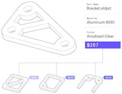
This no longer has to be the case. Online manufacturing platforms are already using AI-powered automatic systems to provide a quote instantly. Taking as input order information (such as part geometry, material, quantity, and other manufacturing requirements), this AI algorithm can predict the price of manufacturing a part in real time. A process that used to take a few hours of work from an engineer is now done automatically in seconds for free.
Part pricing
This AI manufacturing neural network is powered by machine learning and was trained using data from hundreds of thousands of past orders. It is reported to be able to correctly predict the price of machining in more than 90% of all cases. As more designs are analyzed (currently, at a rate of over a thousand part designs per day), the manufacturing neural network keeps learning—improving its accuracy and predictive power with each new submitted order.
This creates a new paradigm in digital manufacturing. While in the past the price of machining was highly dependent on the skill and intuition of the machinists, pricing in an AI-powered sourcing platform closer resembles the stock market. The buyer (in this case, the engineer) and the seller (the manufacturer) come to an agreement on the market price of a commodity in real time using mechanisms of supply and demand.
Things get really interesting if you couple automated real-time pricing with a smart sourcing system that simplifies the way suppliers can accept available incoming orders. This way, engineers can get their designs from CAD to production in less than five minutes and suppliers can fully utilize their manufacturing capacity.
Preparing Your CAD Files for Instant CNC Pricing
So, how can you as a design engineer get the most out of these AI-powered digital manufacturing supply chains? Assuming that you have already optimized your design for CNC machining, the next simple but important steps you’d need to follow are:
- Exporting your models in a CNC-compatible format;
- Preparing a technical drawing; and
- Getting a quote from an online service.
Let’s examine each of these step in greater detail to review the best practices.
Step 1: Export your design to a CNC-compatible CAD file format
Step 1: CNC illustration
The file formats predominantly used in CNC machining are STEP and IGES. These formats are open-source and standardized, and can be used across platforms.
Some manufacturing services also accept 3D models in different file formats, including SLDPRT, 3DM, IPT, SAT, and X_T.
This is very convenient, but keep in mind that your models will probably be converted into the STEP format at some point during the manufacturing process. The best practice is to export your designs as STEP directly from your native CAD software. This way you can inspect them before uploading to make sure there are no conversion errors.
Step 2: Prepare a technical drawing
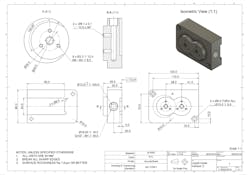
Step 2: CNC technical drawing
Modern CNC machining systems can interpret the part geometry directly from the 3D CAD file with the onboard computer or receive the G-code output of the CAM software. In that sense, a 2D drawing is not needed to manufacture a part with CNC machining.
Yet, it is highly recommended to include a technical drawing in your order as it has information that is not presented in a STEP file. For example, a technical drawing is necessary for the following situations:
- When your design contains threads;
- When tolerances and critical dimensions are defined; and
- When certain surfaces need a specific finish.
Even if your design does not include these elements, it is generally a good practice to include a 2D drawing when placing a CNC order. Most CNC machinists actually prefer them over 3D CAD files, because:
- It is easier to identify the main dimensions, functions, and critical features of a part;
- It is easier to assess the machining operations they perform to manufacture the part; and
- In case of a dispute, the technical drawing is used as the “source of truth.”
Pro Tip: In the example drawing above, the model is fully-dimensioned. This is not necessary when you place a CNC machining order. The dimensions of the part are already conveyed in the 3D CAD file. To save time, you can annotate on your technical drawing only the most important dimensions that you want to be verified by the manufacturer (plus any threads, tolerances, or surface finishes).
If you want to learn more on how to prepare a technical drawing for CNC machining, here is a detailed step-by-step guide. To refresh your memory, here is a quick summary of the steps you should follow:
Step 1: Define and place the most important views of the part.
Step 2: Consider adding section views if your part has hidden geometries.
Step 3: Add construction lines (center lines, center marks and center mark patterns).
Step 4: Add dimensions, starting with the most important first.
Step 5: Specify the exact location and dimensions of all threads.
Step 6: Add tolerances (otherwise the standard tolerance will be ±.125 mm or ±.005 in.).
Step 7: Fill in the title block and add notes for the manufacturer.
Step 3: Get a CNC machining quote online
Step 3: CNC illustration
We already saw how online manufacturing networks make it easier than ever to source your CNC machined parts. All you need to do to receive an instant quote is to upload your files; select material, quantity, and lead time; and specify any other manufacturing requirement.
This technology will save companies time and money, offering them a competitive edge. As technology moves faster, it will not be the biggest or strongest companies that thrive, but the ones able to adapt quickly to change.
Alkaios Bournias Varotsis, Ph.D., is a technical content engineer at 3D Hubs.


